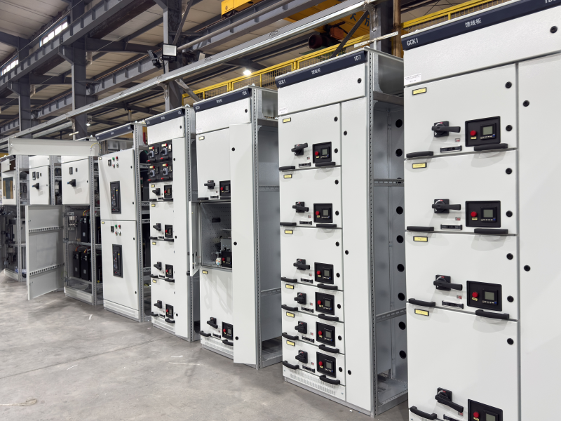
Motor Control Center(MCC)
| Name | Parameter |
| Rated Voltage | 380V/690V (Adapts to North American 50/60Hz) |
| Rated Insulation Voltage | 690V/1000V |
| Rated Current | Horizontal Bus ≤6300A, Vertical Bus 400A-1200A |
| Rated Short-Time Withstand Current | 50kA/1s, 80kA/1s, 100kA/1s |
| Rated Peak Withstand Current | 105kA/0.1s, 176kA/0.1s |
| Protection Level | IP30, IP31, IP40, IP41 |
| Drawer Breaking Capacity | 50kA (Effective Value) |
| Overall Dimensions (Width × Depth × Height) | 600/800/1000×800/1000×2200mm |
| Applicable Ambient Temperature | -5℃~+40℃ |
| Busbar Configuration | Three-Phase Four-Wire System, Three-Phase Five-Wire System |
Introduction
Main Components of MCC
- Motor Control Units Integrated with switches, circuits, relays and contactors to support individual motor starters. It allows centralized start, stop and real-time status monitoring of all motors.
- Horizontal Bus Runs through the full length of the MCC cabinet, distributing main power to each vertical bus section steadily.
- Vertical Bus Also called power distribution bus. It supplies power to multiple starter units and bears the total load of all connected motors and control units.
Core Features of MCC
- Equipped with PLC, VFDs and soft starters, supporting remote operation, online monitoring and equipment fault diagnosis.
- Provides full motor protection against overload and other electrical risks for safer operation.
- VFDs and soft starters enable adjustable motor speed based on actual demand, greatly saving energy and reducing long-term operating costs.